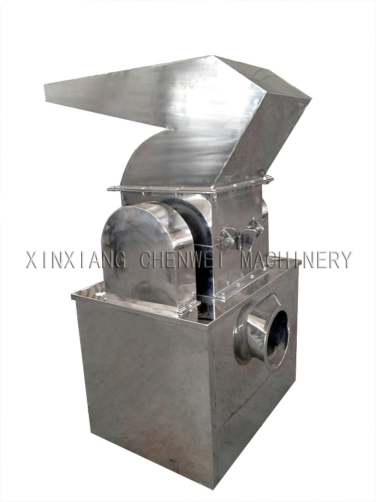
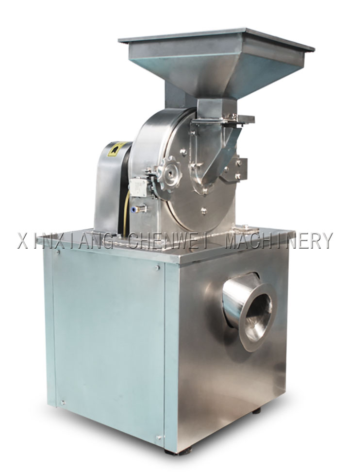
Crushing Machine, in a word, is a kind of machine to grind large size material or granule to smaller sizes or powder. Based on different request, Crushing machine can be divided into different types. Based on different material, different crushing machines are considered to meet different request.
The machine is made up of feeding material part and crush part, and dust collect part. Its coniguration is very briefness, all the parts which contact the material are made of stainless steel.
Crushing Machine Crushing Machine,Stone Crusher Machine,Mobile Crusher,Cone Crusher XINXIANG CHENWEI MACHINERY CO.,LTD , https://www.sieves.nl
For grinder large material into smaller sizes, we can use coarse crusher: This machine is a hammering type mill used to pulverize drugs, chemical materials, food staff and other materials with medium hardness and low viscosity. It is suitable for the suitable for the production in middle and small-batches or sample experiments in laboratories. Materials are fed into the pulverizing chamber by a helical conveyer, and pulverized instead of other energies of other energies of revolving parts of the machine. .
The machine is simple in structure and the pulverizing chamber can be dismounted assemble and be dismounted and cleaned easily. All the parts in the chamber which contact materials are treated specially and corrosion resistama. As a result, in addition Any material ,drifted into grind chamber through feed bucket ,punched by knife edges and knife stands ,cut and grinded simultaneously by revolving and fixed knives, and due to the centrifugal force of revolving object ,automatically runs to exit
If we grind small particles to powder: The crusher mill machine is widely used in pharmaceutical, food, chemical, it can crush various of material.


Control valve: to explore the balance of the circulating system and pressure stability (a)
Preface The nature of control valves The primary goal in designing any HVAC system is to achieve a comfortable indoor climate while minimizing costs and reducing operational problems. In theory, the new control technology seems to be sufficient to meet the most demanding requirements, enabling greater comfort and energy savings. In practice, however, even the most sophisticated controllers do not fully achieve their theoretical performance. The reason is simple: the proper operating conditions that must be met are often overlooked, and its importance for comfort and cost can not be ignored. If we systematically analyze the operation of a HVAC system, we often notice the following problems: Not all rooms can achieve the required room temperature, especially after a high load change occurs. When the desired room temperature can be achieved, it will continue to fluctuate despite the use of sophisticated controls on the end devices. This phenomenon usually occurs in the case of low load and medium load. Although the production plant has sufficient installed capacity, it can not be transported under high loads, especially during the start-up phase. Even sophisticated controllers do not correct these faults. The reason is often related to the design defects of the circulatory system itself, mainly because the three basic conditions have not been met. The traffic at the system interface must be compatible with each other. Design flows must be achieved at all ends. The pressure difference across the control valve must not change too much. Control Valve Features The characteristics of a control valve are determined by the relationship between water flow and valve opening. When the pressure is constant, these two quantities are expressed as a percentage of the maximum value. For valves with linear characteristics, the flow rate is proportional to the valve opening. At low and medium loads, a small opening of the control valve significantly increases the flow through the valve due to the non-linear nature of the end fittings (Figure 1a). Therefore, the control loop under low load may not be stable. This article is mostly about some of the information about the second condition, and some implications for the use of two-way control valves on the end fittings. This problem can be solved by choosing the characteristics of the control valve to compensate for the non-linearity so that the output of the end unit is proportional to the valve opening. At 20% of its designed flow rate, the valve can be set to only allow 20% of the design flow at 50% opening if the end unit output is 50% of its design value. In this way, a 50% calorific value is achieved when the valve reaches 50% opening (Figure 1c). With all these flows, the valve characteristics we receive can compensate for the non-linearity of a typical end heat exchanger. This feature (Figure 1b) is called equal percentage correction "EQM". However, there are two conditions that must be met to achieve this compensation: If the pressure differential across the control valve is not constant, or if the valve size is too large, the control valve characteristics may shift, which may affect the regulatory control performance. The pressure differential across the control valve must be constant. When the control valve is fully open, design flow must be available. Control valve valve authority When the control valve is closed, the end, pipes and accessories reduce the flow and pressure drop. As a result, the differential pressure on the control valve increases. Increasing the pressure differential will shift the characteristics of the control valve. This offset can be demonstrated by controlling valve weights. The numerator is constant and depends only on the choice of control valve and the design flow value. The denominator corresponds to the ΔH achieved on the circuit. The balancing valve installed in series with the selected control valve does not change these two factors and therefore has no effect on the control valve valve power. The selected control valve should be able to achieve the best possible valve authority. According to the range of products supplied by the market, the size is generally large. The balancing valve allows the design flow to be achieved when the control valve is fully open. Its characteristics are closer to the theoretical ones, thus improving the control function (Figure 3b). In an out-of-range allocation (Figure 2a), the remote loop can sustain a higher delta H variation. In the case of low flow, the valve control valve obtained the worst. That is, when the control valve almost withstand all pump head. When using variable speed pumps, the pressure differential near the last circuit is typically kept constant (Figure 2b). In this case, the change in ΔH will be transferred to the first loop. The Δp sensor is used to control the variable speed pump. If it is located close to the last circuit, it is theoretically possible to minimize pumping costs, but problems close to the pump circuit can also be a problem. When the system is operating under a condition of average small load, these circuits may be under-flowed or, if the control valve is designed with the minimum Δp, the valve authority under design conditions will be poor. For this reason, a better compromise is to set the Δp sensor in the middle of the system to reduce Δp by more than 50% compared to a constant speed pump. Figure 2c shows the relationship between power output and valve opening (EQM control valve selected for proper fully open flow with a valve rating of 0.25). When the ΔH obtained on the circuit increases, the control valve characteristics may deteriorate, causing the control loop to oscillate irregularly. In this case, a local differential pressure controller stabilizes the Δp at both ends of the valve so that its valve strength approaches one (Figure 4a).