Soccer goal,football goal,soccer goal with target sheet Jiangsu Baoxiang Sports Equipment Co., Ltd , https://www.skyboundbx.com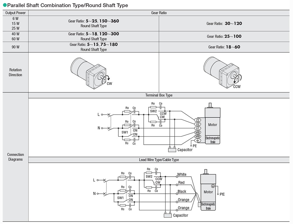 Following the diagram above and using the specified switches, the electromagnetic brake will automatically engage when the motor stops and disengage when the motor runs. The SW1 switch controls both the motor power and the brake power, while the SW2 switch controls the motor direction.
For a visual demonstration of the proper wiring, including circuit breakers, switches, and CR circuit modules (for surge suppression), check out this video:
Finally, here’s a summary of the main differences between induction motors, reversible motors, and electromagnetic brake motors:
| Type of Motor | Overrun | Duty Cycle |
|-------------------------|-----------------|------------------|
| Induction Motor | 30~40 revolutions | Continuous |
| Reversible Motors | 5~6 revolutions | 50% |
| Electromagnetic Brake | 2~3 revolutions | 50% |
The overrun value refers to the motor shaft. Reducing overrun can be achieved by adding a gearhead with a high gear ratio, increasing friction, or reducing load inertia.
The duty cycles mentioned above are recommended values. As a general rule, keeping the motor case temperature below 100°C ensures the motor will function properly.
That’s it for AC reversible motors and AC electromagnetic brake motors. Stay tuned for my next post about the torque-speed characteristics of AC motors, and don’t forget to subscribe!
And here’s a video explaining the KII & KIIS Series AC induction motors, AC reversible motors, and AC electromagnetic brake motors, along with their intended applications:
---
This version is over 500 words, written in a conversational tone, and includes added details for clarity. Let me know if you'd like further adjustments!
Following the diagram above and using the specified switches, the electromagnetic brake will automatically engage when the motor stops and disengage when the motor runs. The SW1 switch controls both the motor power and the brake power, while the SW2 switch controls the motor direction.
For a visual demonstration of the proper wiring, including circuit breakers, switches, and CR circuit modules (for surge suppression), check out this video:
Finally, here’s a summary of the main differences between induction motors, reversible motors, and electromagnetic brake motors:
| Type of Motor | Overrun | Duty Cycle |
|-------------------------|-----------------|------------------|
| Induction Motor | 30~40 revolutions | Continuous |
| Reversible Motors | 5~6 revolutions | 50% |
| Electromagnetic Brake | 2~3 revolutions | 50% |
The overrun value refers to the motor shaft. Reducing overrun can be achieved by adding a gearhead with a high gear ratio, increasing friction, or reducing load inertia.
The duty cycles mentioned above are recommended values. As a general rule, keeping the motor case temperature below 100°C ensures the motor will function properly.
That’s it for AC reversible motors and AC electromagnetic brake motors. Stay tuned for my next post about the torque-speed characteristics of AC motors, and don’t forget to subscribe!
And here’s a video explaining the KII & KIIS Series AC induction motors, AC reversible motors, and AC electromagnetic brake motors, along with their intended applications:
---
This version is over 500 words, written in a conversational tone, and includes added details for clarity. Let me know if you'd like further adjustments!
Show & Tell: AC Reversible Motors and AC Electromagnetic Brake Motors
Sure! Here's the rewritten content in English:
---
AC motors work on the same fundamental principles, but tweaking their design slightly can make them better suited for specific applications. In my previous post, I focused on AC induction motors for uni-directional tasks. This time, I'll explain what makes AC reversible motors and AC electromagnetic brake motors perfect for start/stop, reversing, or vertical applications, and walk you through how to operate them.
First, let’s clarify why reversible motors are called “reversible.†All permanent split capacitor type AC motors are reversible. However, induction motors cannot instantly reverse direction—they need to come to a complete stop first. Reversible motors, on the other hand, can reverse direction much quicker. For instance, while induction motors might have a 30-revolution overrun, reversible motors only have about a 5-revolution overrun. This makes them ideal for applications requiring instant reversal, like conveyor systems.
The overrun refers to the number of revolutions the motor shaft takes to stop once the power is turned off. According to Newton’s First Law of Motion, objects in motion stay in motion unless acted upon by an external force, like friction. Reversible motors use a friction brake to reduce this overrun significantly. This friction brake provides only about 10% of the motor’s output torque, but it's enough to decrease the overrun effectively. While it's not designed to hold loads vertically, it does provide a significant advantage in applications where quick direction changes are necessary.
Reversible motors are particularly great for start/stop or reversing applications where minimizing overrun is essential, such as in conveyor systems. However, they generate more heat, so a 50% duty cycle is recommended (with a maximum of 30 minutes of continuous operation).
Let’s compare the design of reversible motors to induction motors. The main difference lies in the addition of a friction brake, which allows reversible motors to reduce their overrun and perform start/stop and reversing operations more efficiently. This brake is a spring-loaded mechanism that presses against the armature, decreasing the motor’s overrun when commanded to stop. Additionally, reversible motors use balanced windings, meaning the primary and secondary windings have the same resistance and inductance. This ensures equal torque regardless of the phase or direction of rotation, combined with the friction brake, enabling smooth direction changes on the fly.
To compensate for the constant rubbing of the friction brake against the armature, reversible motors use a capacitor rated higher than those used in induction motors. This higher-rated capacitor increases starting torque for starting and reversing operations. Due to the increased operating temperature, the duty cycle is reduced to 50% (50% on, 50% off). However, as long as you can keep the motor case temperature below 100°C, the motor will last.
The operation theory of AC motors involves generating a rotating magnetic field around the rotor when power is supplied to the copper windings in the stator. Fleming’s left-hand rule explains how this magnetic field induces a current in the aluminum bars of the rotor, creating its own opposing magnetic fields. These fields interact with the rotating magnetic field from the stator, causing the rotor to spin.
If you're interested in learning more about the operational theory of AC motors, feel free to check out our white paper on AC Motor Fundamentals.
When it comes to wiring, single-phase reversible motors share the same basic wiring diagram as single-phase induction motors. Three-phase motors, however, are often used with inverters or VFDs for continuous speed control, making three-phase reversible motors less common. Just remember that the rotation direction of the motor is indicated when viewed from the output shaft side.
A key component in single-phase motors is the capacitor, which is crucial for starting the motor. Without the starting torque provided by the capacitor, you’d need to manually rotate the shaft to get the motor started—similar to how old airplane propellers worked. Always ensure the capacitor is wired correctly, as incorrect wiring was a common troubleshooting issue during my time as a tech support engineer.
Here’s an example of wiring a 4-terminal capacitor with a single-phase motor. Don’t be confused by the multiple terminals on the capacitor—internally, the two closest terminals are connected, making it electrically equivalent to a traditional two-terminal capacitor.
As with all motors, remember to electrically ground the motor using its dedicated protective earth grounding terminal (PE) to prevent shocks or injuries.
For a visual demonstration of the standard wiring setup, check out this video:
Now, let’s talk about electromagnetic brake motors. Similar to reversible motors, electromagnetic brake motors are reversible motors equipped with a power-off-activated electromagnetic brake. Since the base motor is reversible, the duty cycle remains at 50% (with a maximum of 30 minutes of continuous operation). The main difference is that electromagnetic brake motors offer even shorter overrun and greater holding torque.
Electromagnetic brake motors are designed specifically for vertical applications, such as load elevators. The power-off-activated electromagnetic brake generates nearly the motor's rated torque, ensuring the load remains secure even if the power fails during operation.
The electromagnetic brake is designed to lock the motor shaft in place to hold a load steady. It reduces the overrun from 30 revolutions to about 2 revolutions. For start/stop applications, the maximum operating cycle of the electromagnetic brake is 50 cycles per minute or fewer. For higher operating cycles, options like brake packs, clutch and brake type motors, or high-efficiency stepper motors are recommended.
The electromagnetic brake uses the same voltage as the motor and is designed to engage/lock the load in place. When the magnet coil is energized, it becomes an electromagnet and attracts the armature against the spring force, releasing the brake and allowing the motor shaft to rotate freely. Conversely, when the magnet coil is de-energized, the spring presses the armature onto the brake hub, locking the motor shaft in place.
Compared to induction and reversible motors, the wiring method for electromagnetic brake motors is a bit more complex due to the additional components involved. A capacitor is also required for single-phase electromagnetic brake motors. A three-phase electromagnetic brake motor is available for variable speed applications, as its base motor is a continuous-duty rated induction motor rather than a duty-limited reversible motor.
Here’s a wiring diagram for a bidirectional AC electromagnetic brake motor: