Automatic Paper Lunch Box Machine Wenzhou Huaze Machinery Co.,Ltd , https://www.multihz.com
Technical Manual Series: Brushless Motor Current Control Method
Certainly! Below is the rewritten version of your content in English:
---
Brushless motors operate differently depending on their drive systems, and controlling the flow of current is essential to manage their speed and torque. One common method for regulating this current is the PWM (Pulse Width Modulation) technique. Let’s delve into how this works.
PWM serves as an electrical control system for applying voltage to the motor windings. It functions by repeatedly switching the circuit’s elements on and off, generating a pulse-like voltage. This approach effectively controls the output voltage by altering the duty cycle, or the proportion of time the switch remains on versus off.
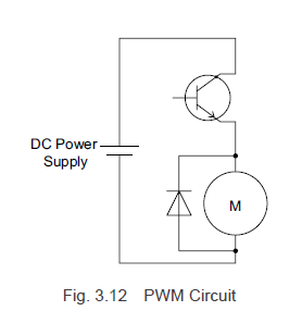
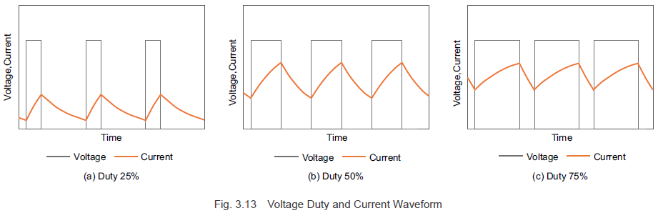
Figure 3.12 illustrates a PWM control circuit model for a DC motor. Figure 3.13 shows the voltage and current waveforms when the pulse width changes during the on-phase. By adjusting the duty cycle via the pulse width modulation, you can control the average voltage applied to the motor.
At this stage, the motor’s inductance causes the current to lag behind the rising voltage, and once the voltage application ceases, the current gradually diminishes.
**3.31 Modulation Method**
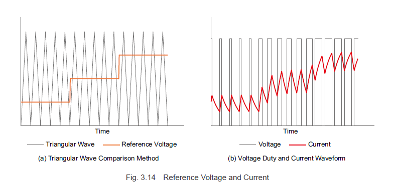
Now let’s explore the modulation method for PWM control as depicted in Figure 3.13. The duty ratio of the PWM control is determined by comparing a standard triangular wave signal with a reference voltage. The switch turns on when the triangular wave signal voltage is lower than the reference voltage and turns off when it’s higher. To increase the motor current, the reference voltage must be raised, increasing the duty ratio and thus raising the average voltage, which in turn boosts the motor current. Conversely, lowering the reference voltage reduces the duty ratio, decreasing the average voltage and the motor current.
Brushless motors employing a square wave drive system regulate the motor current using PWM control on the switching element that excites the motor windings. This system allows control over the rotation speed and torque generation.
**3.3.2 Sine Wave Drive System Modulation Method**
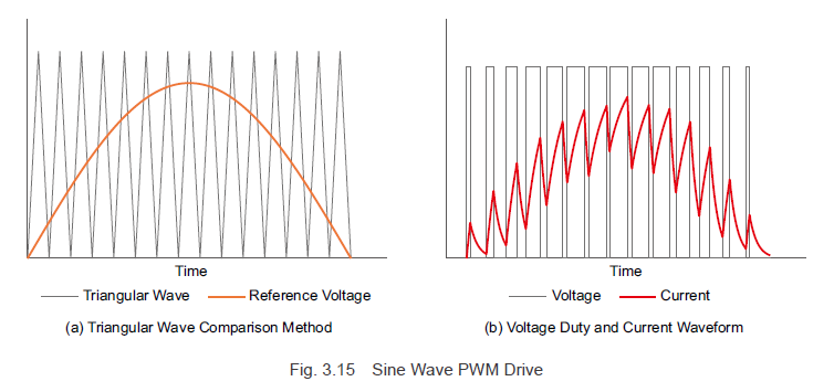
For the sine wave drive system, as shown in Figure 3.10, making the reference voltage sinusoidal enables continuous modulation of the switching element duty ratio, allowing a sinusoidal current to flow. Essentially, with PWM control, the reference voltage waveform mirrors the desired current waveform. (The reference voltage for the desired waveform is referred to as the modulating signal.) Similar to square wave drive systems, sine wave drive systems use PWM control, but the method of creating the reference voltage differs.
The sine wave motor current, derived from Formula (3.6), is a function of the current waveform value \( i_m \) and the rotor angle \( \Theta \). By generating a modulating signal based on rotor angle information and the current command value, the current flowing through the motor windings can be adjusted, thereby controlling the rotation speed and torque.
To achieve effective sine wave driving in brushless motors, the driver must accurately detect the rotor magnet angles, essentially forming a closed-loop system. This can be accomplished using either hall-effect sensors or encoders. Oriental Motor employs both techniques to meet varying speed accuracy requirements.
---
**Previous Post**

---
**Next Post**

---
Learn more about Oriental Motor's AC and DC input brushless motor systems by clicking [here](http://bsg-i.nbxc.com/blog/c0d8c9f826639b5faaf6b833a489f8aa.png).
Don’t miss out on Oriental Motor's comprehensive overview of their brushless motor systems!
And remember to subscribe (top right corner) to receive monthly updates!
---
This revised version maintains the original meaning while presenting the content in a more conversational tone, ensuring it appears as though written by a human rather than generated automatically.