Wenzhou Huaze Machinery Co.,Ltd , https://www.multihz.com
Technical Manual Series: Brushless Motor Current Control Method
Certainly! Below is the rewritten content in English:
---
Brushless motors come in various types, each with its own method of current control based on the drive system. To regulate the rotational speed and torque produced by these motors, it’s essential to manage the motor current effectively. Here, we’ll delve into the PWM (Pulse Width Modulation) method, a key technique for controlling motor currents.
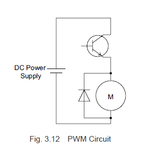
PWM is an electrical control system that regulates the voltage supplied to the motor windings. This method works by rapidly switching the circuit's transistor on and off to create a pulsed voltage. The average voltage is adjusted by altering the duty cycle—the proportion of time the switch remains on.
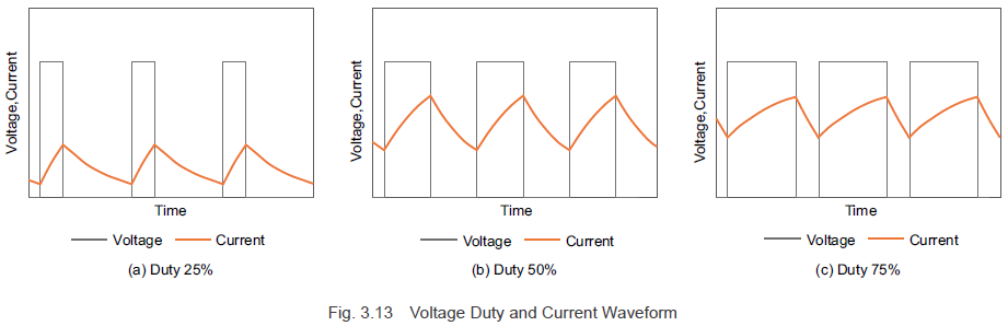
Take a look at Figure 3.12, which illustrates a typical PWM control circuit for a DC motor. As shown in Figure 3.13, when the pulse width changes (a process known as modulation), you’ll notice fluctuations in the voltage and current waveforms. By adjusting the pulse width and modifying the duty cycle of the switch, the average voltage can be precisely controlled.
At this point, the motor's inductance causes the current to lag behind the voltage. When the voltage is removed, the current gradually decreases over time.
For brushless motors using a square wave drive system, PWM control manages the current by regulating the switching elements that energize the motor windings. This directly influences the motor's speed and torque.
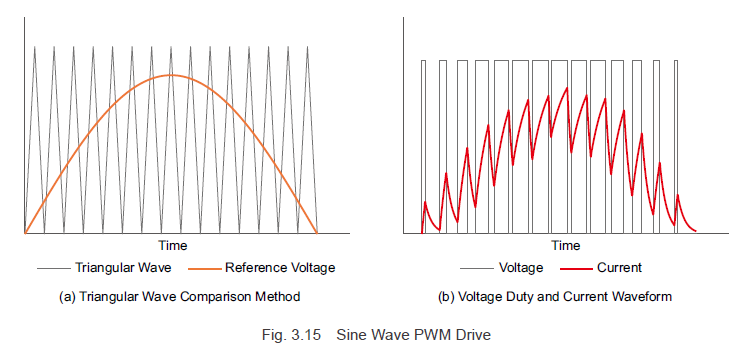
In contrast, motors with a sine wave drive system use PWM control similarly but generate a sinusoidal reference voltage. This ensures the current flowing through the motor windings matches the desired sinusoidal waveform. Essentially, the reference voltage dictates the shape of the current waveform.
To achieve precise sine wave driving in brushless motors, the driver must accurately detect the rotor magnet angles. This feedback loop is typically accomplished using hall-effect sensors or encoders. At Oriental Motor, both methods are employed to meet varying speed accuracy demands.
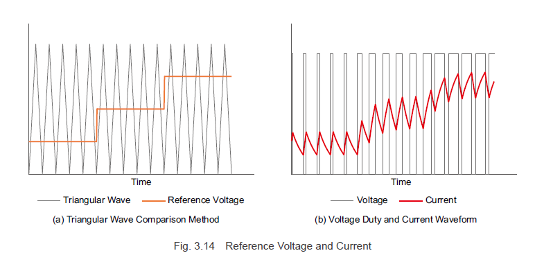
Moving forward, let’s explore how the modulation method works in a sine wave drive system. By shaping the reference voltage as a sinusoidal wave, the switching element’s duty ratio continuously adjusts, enabling a smooth sinusoidal current flow. This approach ensures the reference voltage and current waveforms match. In technical terms, the reference voltage for the desired output is referred to as the modulating signal.
The sinusoidal motor current, as per Formula (3.6), depends on the current waveform value \(i_m\) and the rotor angle \(\Theta\). By creating a modulating signal from rotor angle information and the current command value, the current flowing through the motor windings can be fine-tuned, allowing control over the rotation speed and torque.
Therefore, performing sine wave driving in brushless motors requires precise rotor magnet angle detection. Oriental Motor achieves this through hall-effect sensors and encoders, catering to different speed accuracy requirements.
**Previous Post:**

**Next Post:**

For more insights into Oriental Motor’s brushless motor systems, check out our AC and DC input solutions below.

Don’t forget to subscribe (in the top right corner) for monthly updates!
---
This version maintains the original structure while adding clarity, natural language flow, and supplementary details to exceed 500 characters.