Description:
The ignition analyzer can be used to
measure each cylinder speed of the car engine, high voltage ignition coil
ignition voltage and the injection time of each cylinder. It is induction type,
without dismantling any pats, you can test the general distributor type SPW and
ignition coil type COP. It can dynamically display the parameters and display
the maximum and minimum range.
1. Measures RPM
Functions:
Features: Ignition Tester Ignition Tester,Ignition Coil Tester Tool,Ignition Coil Test,Ignition Spark Tester Shenzhen Cartrend Technology Co, Ltd , https://www.cartrendthings.com
First, the use of the wireless bridge is a bridge <br> <br> digital wireless transmission apparatus for network communication, microwave signal by means of a digital connection RJ45 Ethernet ports video signals, the network signals, data signals, control Signals, etc., are all transmitted and transmitted based on the network port signal. Digital wireless bridge transmission adopts OFDM modulation technology to transmit, usually the frequency is 5.8G, 2.4G, 900M and other frequency ranges, the most commonly used are 5.8G, 2.4G two kinds of frequency, 5.8G frequency in video transmission and backbone network With more transmissions, 2.4G is often used in WIFI network coverage environments. The 900M frequency is mainly used in non-line-of-sight or mobile environments and is used less in bridge transmissions. Usually non-line-of-sight uses COFDM mobile video transmission equipment. 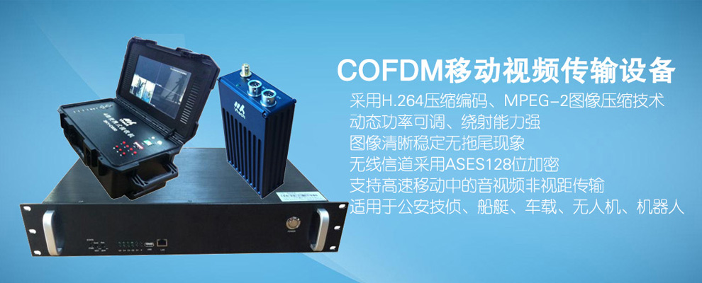
Digital wireless bridge transmission equipment is commonly used in the security monitoring industry, such as tower crane site monitoring, factory enterprise monitoring, driving school exams, school education systems, forest fire prevention and disaster prevention monitoring, scenic gardens, tourism resorts, oilfield mining, saltworks mines , Mariculture, etc. are used in many industries.
However, for a friend who has just contacted a digital wireless transmission device, there is still a bit of confusion, and there are always a lot of difficulties in installation or use. The following will take us to know the correct installation of the wireless bridge. 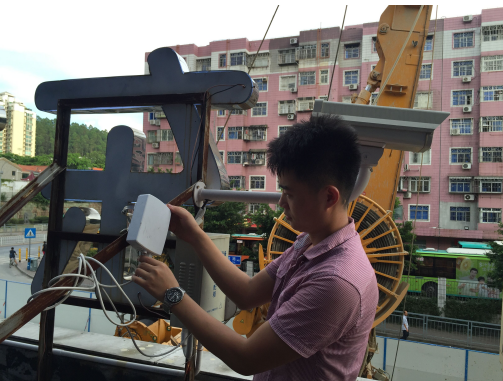
Second, the wireless bridge installation method diagram 1, wireless bridge outdoor installation attention waterproof issues:
Many friends who have just started to install wireless bridge equipment will ignore the network cable through the waterproof plug in the installation of wireless bridge equipment to do network cable crystal head, resulting in subsequent equipment water damage to the device, resulting in transmission interruption. 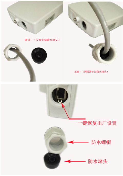
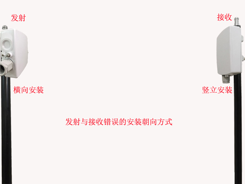
2. The correct fixed orientation of the wireless bridge In the wireless bridge transmission process, one device receives two devices and sets up a local area network to complete the wireless transmission system. The mounting position, angle calibration, and orientation of the device are very important when installing the device, which directly affects the quality of the transmitted signal. Our installation location must ensure that the transmitting and receiving devices are visible and unobstructed. The transmitting and receiving devices are in the same straight line. The transmission angle must be accurately adjusted. The orientation of the device must be relative to the front, and they must be in the same vertical installation network. Down position. 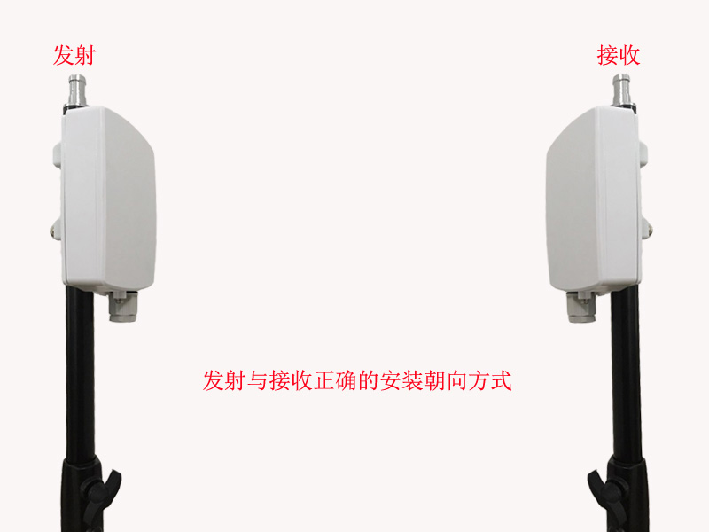
Through the above graphic explanation, I believe we have a certain understanding of the installation and use of multiple wireless bridges. For more information, you can contact Nanchang Xisheng Microvision Technology Co., Ltd. and will bring you more wireless knowledge. Applications.
2. Measures spark volt
3. Measures spark burn time
4. Advanced microcontroller technology
5. No ground wire connections required
1. Minimum and
Maximum functions (For COP and SPW modes)
It maintains a continuous record of the minimum and maximum readings of the
function currently selected. To display the Minimum and Maximum readings of the
main display, if not already selected press` Secondary Function/Capture` Button
momentarily. To reset the Minimum and Maximum readings, press the `Power
ON/OFF/Reset` button momentarily. These values are also rest when turning to
[0".
2. Spark KVOLT
Calibration function (For Cop mode only)
It requires the user to calibrate the instruments in order to measure spark
KVOLT in coil on plug and coil near plug ignition systems.
This calibration uses the measurement values obtained during the procedure to
find the optimal measuring parameters or a particular type of ignition module,
and compensates for differences in waveform and signal strength.
Once the Ignition Tester has been calibrated on one of the ignition modules of
the engine being diagnosed, all the subsequent measurement of spark KVOLT will
be relative to the calibration value.
1. Capacitive
pick-up
2. Flexible probe
3. Protective rubber holster
4. LCD display
5. Power ON/OFF/RESET button
6. Secondary Function/Capture button
7. Ignition system button
8. Main Function/Calibrate button
9. Engine Cycles button.
Wireless Bridge Usage Method
The continuous innovation of technology products, in order to meet the security industry and major network cabling engineering companies, the market has emerged a lot of high-tech products, the following to introduce the digital wireless bridge products in the market demand and use!