CZ Purlin Forming machine,we can tell from its name,that means one machine can make c purlin and z purlin both.It is very easy to convert from c purlin to z purlin or z purlin to c purlin.Automatic control while changing different sizes.
The final product can be cut as per set length controller,and the length is automatically measured by encoder.When final product reached set length,machine will stop to cut the sheet automatically.Finish thhis action,the machine will run again continuously
CZ Purlin Roll Forming Machine Cz Purlin Roll Forming Machine,C Z Interchangeable Used,Cz Purlin Sheet Roll Forming Machine,Changeable Purlin Roll Forming Machine Botou Golden Integrity Roll Forming Machine Co.,Ltd , https://www.jcxsteelrollformer.com
Practice <br> <br> 1 cable operator should follow while continuing to be specially trained to grasp essentials and practices action.
When the number of cores is the same, the corresponding color fiber in the bundled tube must be the same; when the number of cores is different, the number of cores is first welded in order to connect the number of small cores. The common optical fiber cables are stranded, skeleton, and central tube bundle type optical fibers. The colors are divided into blue, orange, green, brown, gray, white, red, black, yellow, purple, pink and blue in order. Multi-core fiber optic cables put different colors of optical fibers in the same tube bundle into a group, so that there may be several tube bundles in one optical fiber cable. Right on the cross-section of the cable, the red beam tube is regarded as the first tube bundle of the optical cable, clockwise, green, white 1, white 2, white 3 and so on. 
Firstly, clean the cutter and adjust the position of the cutter. The cutter should be placed steadily. When cutting, the action should be natural, steady, not heavy, and not rush, avoiding the occurrence of bad end faces such as broken fibers, bevels, burrs, and cracks. Also learn to "play the piano", rational distribution and use of your own right hand fingers, so that it corresponds to the specific parts of the incision, coordination, improve the cutting speed and quality.
2 Fiber Cable Connector Box Preparation
Fiber cable splice box preparation preparations include shearing, stripping, fiber stranding, and securing of tail cable. Before the specific operation, it should be "a check, second look." That is, first check the drawing data, understand the cable model, and determine the connector type. Then look at the actual cable route: in/out, the end of the branch cable tag and whether there is too short, too long, diffuse pole, stranded wire, etc., and finally refer to the follower box structure to determine the successor box on the rod The pre-fixed position makes it clear and clear to enter/exit the aerial cable, and the branches are naturally smooth, and the curvature is scientific, beautiful, and generous. The end of the treatment, the specific operation should grasp the "cut, cut, pull, solid, disk" five links. 
"Cut", the removal of the remaining cables, should be neat, to ensure that the optical fiber completely disconnected, should not be in the case of "broken off the wire even" under the conditions of dragging the cable, to prevent injury and internal fiber. Observe whether there is any injury to the fiber optic cable.
“Cutâ€, the circumcision of the optical cable, should grasp the intensity and depth, adopt the “Layered Progressive†method, and should not be determined to strengthen the position of the core to prevent damage to the cutting knife. The feeling of slicing should be strengthened to feel the difference between the knife and the shield.
"Pull out", PE plastic protective layer should pay attention to methods and techniques. Under difficult circumstances, the "one-point," "second-shake," and "three-peel" methods may be adopted, that is, segmented loop cutting and unplugging, and the separation of the cable heads to separate the various layers will not allow vertical stripping. It is very simple and effective under the harsh conditions in the wild. 
“Fixedâ€, when the optical cable is fixed in the splice box, waterproof must be done first, and the reinforced core is fixed (the reinforcing core cannot be too long to prevent damage to the core), and the plastic pipe is fixed.
"Plate", open stripping plastic cleaning grease, coiled to determine the location of the welding point, to prevent the joint position after the connection is not at a predetermined fixed point.
3 Cable connection process 1) Strip the optical cable and fix the optical cable to the fiber shelf.
The common optical cables are stranded, skeletonized, and center-beam-type optical cables. Different optical cables should adopt different stripping methods. After stripping, the optical cables should be fixed to the fiber trays. 
2) Fibers pass the fiber through a heat shrink tube. Separate the different fiber tubes of different colors and pass through the heat-shrink tube. After the welding is completed, the heat-shrink tube can be used to protect the optical fiber fusion joint. 3) Turn on the fusion splicer power supply and select the proper welding method. There are two kinds of AC and DC power supply for the fusion splicer, and it is necessary to switch the power supply according to the type of power supply. We know that conventional types of single-mode fibers and dispersion-shifted single-mode fibers have operating wavelengths of 1310 nm and 1550 nm. Therefore, we must choose the proper fusion splicing method according to the fiber and operating wavelength used in the system. 
4) Prepare the fiber end face. The quality of the fiber endface will directly affect the quality of the connection, so before welding, you must first make a qualified endface. Strip the coating with a special wire stripping tool, wipe it several times on the bare fiber with clean cotton-stained cotton, and cut the fiber with a precision fiber cleaver. Cut the length of the 0.25-nm (outer coating) fiber. 8mm-16mm, for 0.9mm (overcoat) fiber, the cut length can only be 16mm. After cutting the fibber can not touch any object, it should be immediately put into the welding machine. Alcohol should use high concentration of industrial alcohol to prevent alcohol from leaving water after evaporation, affecting the welding effect. 
5) Place the fiber. Place the fiber in the V-groove of the fusion splicer. Carefully press the fiber platen and the fiber clamp. Set the position of the fiber in the platen according to the cut length of the fiber and place it properly in the windshield. During the process, the fiber head should be as close as possible to the centerline of the electrode but it should not be exceeded. When placing the core, the ring finger refers to the welding machine to prevent hand shaking.
6) Follow the fiber. After pressing the bond button, the fiber moves towards each other. During the movement, a short discharge cleans the surface of the fiber. After the gap between the fiber ends is suitable, the dissolver stops moving towards the opposite direction. The initial gap is set, the fusion splicer measures, and the cut is displayed. angle. After the initial gap setting is completed, the core or cladding alignment is started, then the fusion splicer reduces the gap (final gap setting), the arc generated by the high voltage discharge fuses the left fiber to the right fiber, and finally the microprocessor Calculate the loss and display the value on the display. If the estimated loss is higher than expected, it can be discharged again and the welder will still calculate the loss after discharge. 
The quality of the visual inspection of the joints from the new welding a, joints with traces b, axial displacement c, joints into a ball d, the joints with bubbles e, joints thicker than the normal fiber, f, the joint thinner than the normal fiber. The main causes of the above problems are: a. Discharge is not in place, generally it can be discharged (ARC)b, there is dirt in the welder's V-groove, or the X/Y field motor of the welder is unbalanced, and “self-diagnosis experiment†can be performed. c. Because the end face of the fiber is too miscellaneous, the basic discharge is unsuccessful and can only be redone. d. In a long-term situation, discharge calibration can be performed due to non-uniform discharge. e. The electrodes need to be replaced or the objective lens dust is too much. A small knife can be used to slightly scrape the top of the electrode. 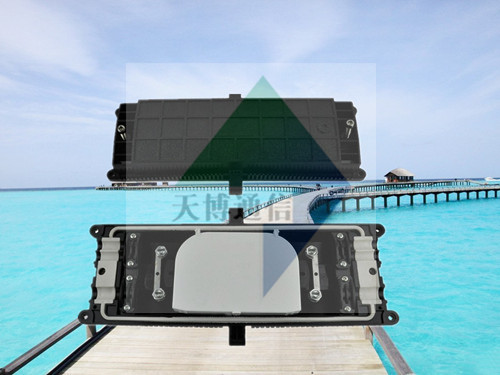
7) Remove the fiber and use a heater to reinforce the fiber. Open the windshield and store the welding data at the same time. These include: splice mode, data, estimated losses, etc. Remove the optical fiber from the fusion splicer, place the heat shrink tube at the center of the bare fiber, place it in the heater, and remove the optical fiber from the heater after the completion. During operation, do not touch the heat shrink tubing and the ceramic part of the heater due to the high temperature.
8) Fibers are fixed and fixed. Connect the connected fiber tray to the fiber storage tray, fix the optical fiber, containment tray, splice box, terminal box, etc., and complete fiber fusion.
9) Test. Optical fiber measurement using the optical time domain reflectometer OTDR can be divided into three steps: parameter setting, data acquisition, and curve analysis. The optical time domain reflectometer OTDR manually sets the measurement parameters including: 1 Selecting the wavelength λ: Because different wavelengths correspond to different light characteristics, the corresponding wavelength is selected, and the test accuracy is higher. 2 PulseWidth; the longer the pulse width, the larger the dynamic measurement range, the longer the measurement distance, and the greater the blind area. If you need to test a longer distance, select a larger pulse width. Correspondingly, if you need a higher test accuracy, select a smaller pulse width. 3 Range: The OTDR measurement range refers to the maximum distance that the OTDR acquires data samples. The measurement range determines the size of the sampling resolution. Practice has proved that the measurement range is between 1.5 and 2 times the length of the fiber to be measured. 4 Average time: Generally speaking, the longer the average time, the higher the signal to noise ratio. The acquisition of 3 min will be 0.8 dB more dynamic than the 1 min gain. Generally set to 3 minutes. 5 Fiber parameters: The settings of the fiber parameters include the refractive index n and the setting of the backscatter coefficient n and the backscatter coefficient η. The refractive index parameter is related to the distance measurement, and the backscatter coefficient affects the measurement result of the reflection and return loss. These two parameters are usually given by the fiber manufacturer. 6 Positive Gain Phenomenon Processing Positive gain may occur on the OTDR trace. The positive gain is due to the fact that the optical fiber after the splice point generates more backward astigmatism than the fiber before the splice point. At this time, it is necessary to measure in both directions and average the result as the splice loss. 
4 <br> <br> cartridge seal cartridge is in the subsequent finishing, stress "tight" word, when operating both inside and outside two aspects. In: Before the sealing box, check whether the optical fiber is exposed, and whether the entire remaining disk is fixed? Whether it is placed right in place in the box, whether the filling glue is even, especially if the cable is entangled with the root of the cable, whether the concave and convex parts of the box body are consistent or not, and it is necessary to seal and not make it difficult to close. Outside: refers to the box body should pay attention to the method of sealing, the screw type, to use the cyclical progressive force method, so that the box body evenly, beware of breakage. For snap-in, winter construction, if necessary, preheat the baking card holder.
12 core cable connector box
Fiber fusion welding methods are generally welded, active connection two. In the actual project, the welding method is basically adopted because the welding method has a small node loss, high reflection loss, and high reliability. I think that the following aspects should be taken into account when improving the quality of fiber optic cable connections.