With China HAE Wall Printer you can color and animate your home environments. You can print on wall, reproduce directly onto walls any colors images favorite, changing and
render unique your intimate spaces. As a digital fresco, but you can choose the photos. Any digital file you want, any size you prefer and any surface you have, Then Mural Printer and canvas printing machine can print it out in high quality colors durable, Direct to wall inkjet printer can be used in homes, offices, hospitals, schools, restaurants and cafes, Gyms, shipping centers , Childcare centers etc.
Horizontal Wall Printer,3D Horizontal Wall Decor Printer,Horizontal Water Based Ink Wall Printer,High Resolution Horizontal Wall Printer Wuhan HAE Technology Co., Ltd. , https://www.whwallprinter.com
Because of its unique performance, vortex flowmeters have attracted people's attention and have been widely used. However, there are still two problems that plague people. One is that the flow field is distorted due to the interference of the flow blocker at the upstream of the instrument. , affect the normal vortex away. In order to overcome the disturbance of the flow field, a longer straight pipe (generally 15 to 40 times the length of the inner diameter of the process pipe) needs to be fitted in front of the meter, which is difficult to satisfy in the actual site. Second, one of the main features of vortex flowmeters is the wide range, which is generally around 10:1. It should be said that such a wide measurement range should be a relatively good performance, but in practical industrial applications, the maximum flow rate is much lower than that of the instrument. The upper limit value and the minimum flow rate are often lower than the lower limit value of the instrument. Some instruments often work near the lower limit flow rate, causing the meter's measurement accuracy to decrease. At this time, the signal is weak and the instrument's anti-interference ability is also reduced. In order to measure the small flow rate, people often use the traditional reducer tube whose inner cavity shape is a garden stage, and after the diameter reduction, the flow velocity at the measurement place is increased. The vortex flowmeter is operated within the normal flow rate range. However, this reduction method has a large structure size (general length is 3 to 5 times the inner diameter of the process tube), and at the same time, the fluid flows through the reducer tube and is at a reduced diameter. A large number of swirling flows are generated, increasing the local resistance loss and also distorting the flow field. Therefore, a straight pipe with a length of more than 15 times the inner diameter of the process pipe must be installed between the reducer and the meter for rectification, and the resistance loss along the way is increased (as shown in Fig. 1). This method increases the construction cost and also provides processing. , installation inconvenience. 
Second, the principle and analysis First, it should be pointed out that the traditional reducer can be reduced diameter, and with a smaller diameter flow meter to achieve the purpose of measuring small flow, but this method can not increase the instrument's turndown ratio, because it At the end, the flow velocity distribution of the pipeline is changed. We know that the theory and derivation of vortex flowmeters are based on infinite uniform flow fields. In actual closed circular tubes, however, they are non-uniform flow fields. The cross-section flow velocity distribution is a revolving paraboloid, although the choice is reasonable. The columnar shape makes the velocity distribution of the arcuate surface on both sides of the cylinder uniform, but in fact, the influence of the flow velocity distribution on the paraboloid of revolution on the process pipeline is objective. Experiments show that this effect is smaller when the flow rate is relatively large, or that the effect is within the allowable range. However, as the flow rate decreases, this effect becomes larger and larger. From a large number of calibration data, the instrument constant always follows. The decrease in flow increases. This shows that the difference between the flow rate at the sampling point and the average flow rate is increasing.
After using a reduced-rectifier rectifier (see Figure 2), since the flow rate at the converging section gradually increases, the increase in flow velocity at each point on the section is not the same. The increase in flow velocity near the center is small, and the flow velocity increases near the edge of the throat diameter. Big. 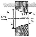
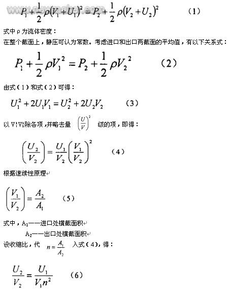
The speed unevenness at the exit will be reduced by n2 times. Therefore, the flow velocity at the outlet tends to be even, and it is closer to the theoretical uniform flow field conditions of the vortex flowmeter, which not only makes the vortex stable, but also improves the measuring range of the instrument. In addition, such a reduced-rectifier rectifier effectively suppresses disturbance during the conversion of fluid kinetic energy.
Third, the experimental positive example 1: a caliber 40mm vortex flowmeter installed in the φ40 process piping, calibration accuracy of 1% to meet the ratio of 8:1, when installed in the φ50 process pipeline, and in the instrument With adjustable rectifiers on both sides, the accuracy is 1.0% over a 15:1 range.
Example 2: After two sets of 50mm and 40mm vortex flowmeters are fitted with rectifiers, they are respectively installed on the 80mm process pipelines for water calibration. The experimental data is shown in Table 1. 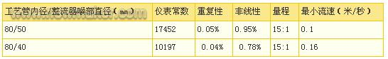

1. When the flow rate of the pipeline is low, a variable-ratio rectifier is used so that the instrument characteristics are generally kept in good condition;
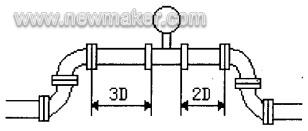
2. Using a variable-ratio rectifier, the flowmeter in the upstream of the instrument is in the form of two 90° elbows in a plane, and the straight pipe is very short (3D). The offset of the meter constant is about 0.7%, indicating that the rectifier has good The flow adjustment performance. (The same type of upstream spoiler as the experiment does not contain the rectifier. When the length of the upstream straight pipe is 8 times the inner diameter of the process pipe, the meter constant offset is 2.0%!)
3. Install a variable-diameter rectifier in front of the instrument to display the measuring range of the instrument.
This is consistent with theoretical analysis.
Fourth, the resistance calculation Set the process pipe diameter D1, the density of the medium is Ï, the flow rate of V1 vortex flowmeter pressure loss is ω1, the rectifier pressure loss is ω3, the total pressure loss is ω.
?ω1=0.3ÏV21(Pa)
After the rectifier is used, the diameter of the instrument is D2, then the velocity at the vortex flowmeter is V2 and the pressure loss is ??2.
?ω2=1.3ÏV22=(V2/V1)2??ω1=(D1/D2)4??ω1
The pressure loss of the rectifier depends on the reduction ratio D2/D1, and the value is generally above 0.8. The pressure loss of the rectifier is:
?ω3=0.12?ω2
Therefore, the total pressure loss ω is: ω = 1.12 ω 2 = 1.12 (D1/D2) 4 × 1.3 ÏV 21 (Pa)
Example: A water metering system with a diameter of D1=100mm uses a vortex flowmeter as a flowmeter. Its maximum flow velocity Vmax is 1m/s, and its minimum flow velocity Vmin is 0.3m/s. It is proposed to use 100/80 rectifiers to calculate each Related parameters:
The reduced flow rate is V2:
V2max=(100/80)2×1=1.56m/s
V2min=0.47m/s
Ωmax=1.12(D1/D2)41.3ÏV21
=1.12(100/80)4×1.3×998×1=3547(Pa)
V. Application examples Installation of variable-ratio rectifiers Full-tube vortex flowmeters have been widely used for the measurement of gases, water, and vapors, and their examples are not exhaustive. They have all received satisfactory results.
What is more worth mentioning is that the variable-rectifier rectifier is used with a plug-in type vortex flowmeter (see Fig. 4) for large-diameter gas measurement, successfully solving the problem of large-diameter gas media dirty, low flow rate, and large flow variation. Allowing pressure loss to be small and so difficult.
In the metallurgical industry, the orifice meteor is usually used to measure large diameter gas. Due to its own limitations, it is difficult to meet the actual measurement requirements. The problems are: 1 The gas contains dust and various impurities. After a period of time, a large number of Dust deposits on the upstream side of the orifice plate, and various impurities are attached to the surface of the measuring element. In terms of the orifice plate, there is no accuracy at all, and at the same time, the problem of clogging of the conduit often occurs. Due to the continuity of production, it is not possible to stop cleaning or replace the orifice. 2 Because of the low flow rate of the medium, in order to obtain a larger differential pressure, the aperture of the orifice plate is generally relatively small, resulting in large pressure loss. When the flow rate increases, the orifice plate does not function as a current limiting device. Some companies have to remove the orifice plate to meet production. 3 Ordinary orifice flowmeters have a range of approximately 3:1, often failing to meet actual operating conditions.
The gas flow measurement system composed of adjustable diameter rectifiers and plug-in type vortex flowmeters has been put into operation: 1 The inlet of the reducing rectifier is a smooth curve, and the medium has a self-cleaning effect when flowing through it, without causing dust accumulation. 2 The flow rate increase at the reduced diameter can meet the requirements of the lower limit flow rate of the plug-in type wavble flowmeter. The vortex flowmeter has a 10:1 turndown ratio, which fully meets the requirements of the gas measurement range. 3 The plug-in vortex flowmeter can remove the probe for regular or irregular cleaning with constant flow of the pipe. Meet the requirements of continuous production. 4 The pressure loss is small. The flow resistance of the probe part of the plug-in type vortex flowmeter in the large-diameter pipe is negligible. The reduction ratio of the reducing part is generally greater than 0.7, and the maximum flow rate of the pipe is calculated at 25m/s. Pressure loss is only within 200Pa.
The above shows that this method is an effective method to solve large-scale gas metering.
6. Conclusion Vortex flowmeters are used in conjunction with variable-ratio rectifiers to form a new flow measurement system that allows the lower limit of flow measurement to be reduced (as the original 1/3) and the measurement range is expanded (15:1 or more). And can greatly reduce the instrument to the upstream straight pipe length requirements. This is undoubtedly a big improvement for a flowmeter. It broadens the scope of application of vortex flowmeters in gas, city gas, water, hot water, steam, oil, milk, liquid, chemical products. (The above mediums generally require low flow rate at the lower limit and a wide measurement range.) The flow measurement will play a prominent advantage. The actual application of adjustable-rectifier rectifiers in industrial users also shows that the reduced-diameter rectifier simplifies the instrument installation process and greatly reduces the project cost.
Research and application of variable-ratio rectifiers are typical examples of flow application technology research. It is necessary to further deepen its own research. At the same time, we should also pay more attention to the application of other flow-related technologies and make full use of existing technologies. The equipment resources really solve some difficult problems in flow measurement.
Application example of reducing rectifier in flow measurement
Keywords: Reduced flow rectifier flow measurement I. Overview Traditional flow rectifiers have matured after long-term research and practice. They generally use barriers to separate flow channels to adjust the velocity distribution in the pipeline to achieve the purpose of rectification; Rectifiers are mainly used in laboratory and flow calibration systems. However, this method is apt to cause dirt clogging and increase resistance loss, so it is rarely used in industrial pipelines. Longitudinal end face adopts special-shape line reducing rectifier (has been declared as national patent), has multiple functions of rectifying, increasing flow velocity and changing flow velocity distribution, its structure size is small, the length is only 1/3 of the inner diameter of the process tube, and can be directly clipped At both ends of the meter, it is not only necessary to add an additional straight pipe, but also to reduce the requirement of the meter for the upstream straight pipe. Experiments show that the upstream resistance of the instrument is two 90° elbows in one plane. Under normal circumstances, the upstream side of the vortex flowmeter should be equipped with more than 20 times the length of the pipe, and the vortex flowmeter is installed. Reducing the diameter of the rectifier greatly reduces the requirement for measuring the length of the upstream pipe, and its resistance is much smaller than that of a conventional reducer. More importantly, the lower limit flow rate can be reduced to 1/3 of the original, and the turndown ratio can be increased to more than 15:1. Set the pressure at the inlet of the rectifier to P1, the average flow velocity is V1, the velocity unevenness at a certain point is U1, the pressure at the outlet is P2, the average flow velocity is V2, and the velocity at the outlet is not the same through a certain flow line at an inlet point Uniformity is U2, along the streamline, derived from the Bernoulli equation: From equation (6), the effect of shrinkage ratio on the uniformity of the velocity at the outlet, ie, for a certain degree of non-uniformity of the inlet velocity, Then two φ50mm and φ40mm vortex flowmeters are equipped with rectifiers, and they are respectively installed on φ80mm pipelines. The upstream of the instrument is two 90° elbows in one plane, and the front and the second of the adjustable rectifier are The 90° elbow distance is 3 times the length of the inner diameter of the process tube, and the water calibration is performed. The process map is shown in Figure 3, and the experimental data is shown in Table 2. Experimental results show: