1. Grouting pipe use specification: Φ20×3000 grouting pipe for over-excavation over 500mm, over-excavation less than 500mm and Φ20×2500 grouting pipe for bottom plate, grouting pipe row spacing is 2m×2m, error ±100mm, exposed length 100m ~ 150mm. 2. Grouting pipe arrangement: one vault, one for each gang along the contour line 2m, one for each 0.5m from the bottom plate, 7 for each row, 3 for each row, total Row 10. (2) Grouting materials and ratio: Grouting configuration: first according to the ratio of water: cement = 1: 0.8 ~ 1.5 (weight ratio). Add the clean water to the mixing tank, add the filtered (grid) cement in proportion, stir evenly, and then start grouting. At the beginning, the water ash is tested from small to large. (3) Grouting process: 1. Grouting hole → installation ∕ fixed grouting pipe → dressing grouting pipe head thread / plug temporary sealing → 8h → spray grouting after spraying (mixing). 2. The rock powder in the grouting pipe should be blown clean, and then the grouting pipe is fixed firmly. The threaded part of the grouting wire is wrapped with plastic cloth, and then the roadway vault and the grouting pipe at both shoulders are installed. After the grouting pipe is finished, the grouting pipe must be fixed in the hole with the stoppers (1-3 pieces), and the outside of the plug is level with the wall of the roadway to prevent overflow during grouting. After the grouting pipe is inserted, the grouting pipe hole must be temporarily sealed with a wooden plug or rag to prevent the paste hole from being clogged. 3. Each row of grouting should start with the first grouting pipe in the lower part of the gang, and then fill the second one, then grout from the other gang to the vault. For different rows of grouting pipes, odd rows are placed on the first day and even rows are placed on the next day. Construction quality requirements: 1. The grouting pipe must be perpendicular to the contour of the roadway. Each grouting pipe must be injected with the pressure value of the design expressed by the pressure or the grouting pump does not enter the grouting. 2. All top grouting pipes shall be constructed according to the design requirements of position and angle. The tolerance is ±100mm. 3. It is strictly forbidden to use expired or agglomerated cement. 4. Grouting equipment and pipelines must be cleaned to ensure the equipment is in good condition. 5. All materials and tools at the construction site must be neatly arranged to ensure civilized construction. 6. Make the slurry: Add the clean water to the mixing tank according to the ratio, then put the cement into the mixing vessel through the feeding grid, mechanically stir, mix and stir evenly, and stir the time for not less than 5 minutes. Installation, use and maintenance of grouting pumps and grouting machines (1) The grouting pump should be placed in a stable position and fixed in a proper position. The arrangement of the suction and discharge pipeline, the mixer and the pulp cylinder should be reasonable, and the pipeline should be twisted, folded, crossed, etc. The vertical distance (suction stroke) from the suction head to the grouting cylinder shall not exceed 1 m, the vertical distance from the grouting hole to the center of the grouting cylinder shall not exceed 50 m, the length of the suction pipe shall not exceed 5 m, and the length of the slurry pipe shall not exceed 200 m. (2) Fuel tank refueling. Unscrew the small cap on the fuel tank and add a clean No. 46 hydraulic oil (the upper edge of the oil mark) to the tank through the strainer. Change oil every 15 days to 30 days during use and clean the inside of the tank and the strainer. (3) Commissioning 1. Open the protective cover. 2. Rotate the relief valve pressure adjustment knob counterclockwise to the limit position (zero pressure state). 3, each lubrication part, oil cup, etc., add enough lubricant. 4. Jog the motor and check the pulley steering to see if it is in the same direction as the gear pump, otherwise correct it. 5. After the steering is correct, check whether the rotation is flexible, then stop the piston rod in the middle position, and push and pull the reversing mechanism by hand to see if it is flexible and reliable. 6. Place the suction head in the water purifier and open the slurry valve on the mixer to close the grouting valve. 7. Start the motor and slowly rotate the relief valve pressure regulating handle clockwise to make the grouting pump work normally (that is, the piston reciprocating frequency reaches 20 times/min, the hydraulic system pressure reaches 1.5~2Mpa), run for more than 3 minutes, and check each part. Is it working properly? 8. Close the mixer slug valve and adjust the high pressure handle of the overflow valve so that the index pressure of the mixer reaches the predetermined grouting pressure and tighten the lock nut. Then stop the pump and install the shield to prepare the grout. (4) Normal operation 1. After opening the pump, open the grouting valve of the mixer, close the slurry valve, and test the water for more than 1 minute. 2. After confirming the normal test run, quickly put the suction head into the slurry cylinder (the cement slurry must be stirred), open the slurry valve at the same time, close the grouting valve, and observe the slurry condition. 3. After connecting the grouting pipe and the grouting hole, open the grouting valve, close the grouting valve, and start grouting. (5) Grouting pump maintenance 1. When the grouting of each grouting hole ends or the pump is stopped for any reason, the suction head should be immediately moved into the clean water cylinder, and the valve should be opened, closed and grouted separately, and the pump can be washed for more than two minutes until the slurry is discharged. The water discharged from the door is clear. 2. After all the grouting is completed, wash the pump in the same way as above, and then remove the suction head.
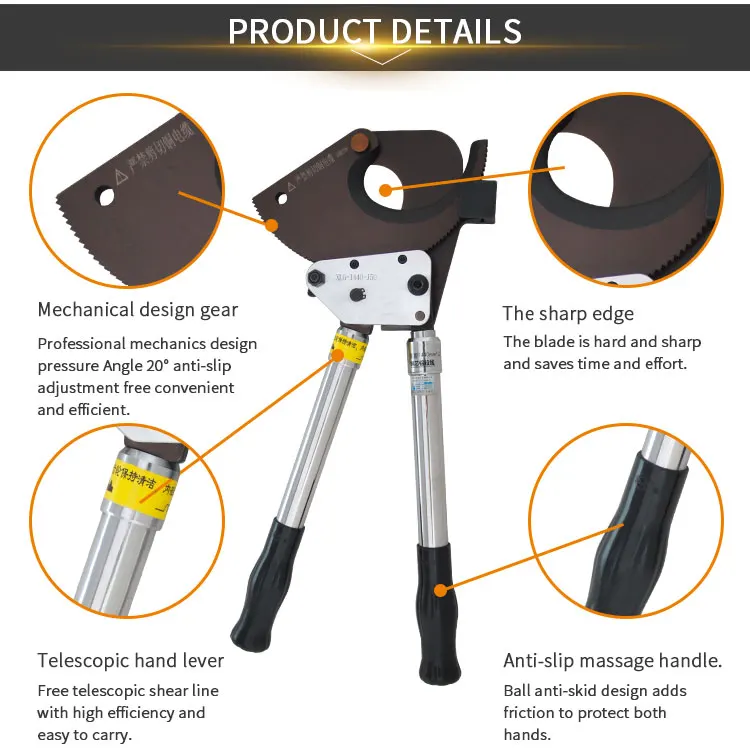
The main material of the product is carbon steel.
The handle of the product is telescopic.
The design of the handle is hard and light.
Packing: Ratchet Cable Cutterpacked by carton or as your request.
Applications: Electric power industry,Mommunication industry,Mhip-building industry,Metaluraical industry.
Features:
1. Cutting easily with forging blade and long lifetime
2. Not for cutting steel or steel wire
3. With safety lock
4. Cutting Range:240mm² max.
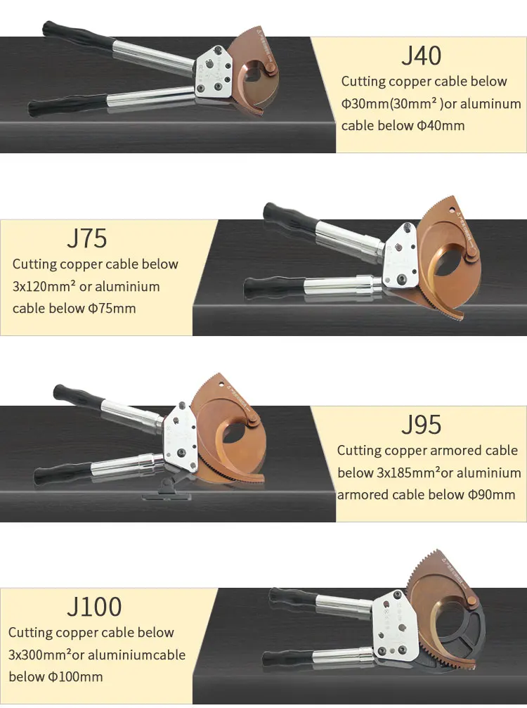
Ratchet Cable Cutter Different specifications as below:
Ratchet cable cutter
Model
Size
Weight
J12
345(514)*125*46mm
1.95kg
J30
405(514)*160*64mm
3.6kg
J13
345(514)*125*46mm
1.95kg
J25
745*135*50mm
3.45kg
J50
400(570)*158*52mm
3.2kg
J40
260*100*35mm
1.15kg
J40A
245*135*42mm
1.05kg
J40B
250*95*30mm
0.65kg
J75
420*205*50mm
3.6kg
J95
818*265*50mm
5.43kg
J100
490*270*50mm
6.4kg
J130
500*300*50mm
8.1kg
J160
500*300*50mm
8.11kg
Ratchet Cable Cutter Details:
Ratchet Cable Cutter Ratchet Cable Cutter,Cable Cutters,Ratchet Cutters,Ratchet Wire Cutters Hebei Long Zhuo Trade Co., Ltd. , https://www.hblongzhuo.com


Safety technical measures for grouting construction of new well bottom yard
(1) Size and arrangement of grouting pipe: